
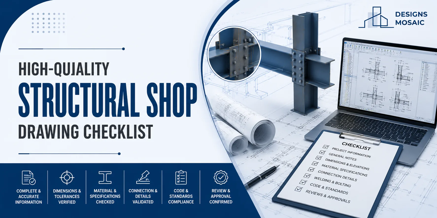
Bad shop drawings don’t announce themselves. They pass through submittals, get approved with comments, and quietly set up problems three weeks later when the steel fabricator builds something that doesn’t fit.
Most contractors have been there. A connection detail that looked fine on paper, a member size that didn’t account for field conditions, an anchor bolt pattern that conflicted with the slab pour. None of it catastrophic on its own. All of it expensive. Good structural shop drawings services exist precisely to stop that sequence before it starts.
What Shop Drawings Are Actually Supposed To Do?
Here’s a distinction that gets lost sometimes. Shop drawings are not design documents. They’re fabrication documents. Their job is to translate the engineer of record’s design intent into instructions precise enough that a fabricator can build, a contractor can install, and an inspector can verify, without calling anyone for clarification.
When a shop drawing requires a call to clarify, it has already failed at its basic function.
That sounds obvious. In practice, it’s harder than it looks. A structural shop drawing set for a mid-sized commercial project can run hundreds of sheets. Connection details, member schedules, anchor bolt layouts, erection drawings, weld symbols, finish specifications. Each sheet is a potential breakdown point between design intent and field reality.
The quality bar, then, is not just technical accuracy. It’s communication clarity under conditions where the person reading the drawing may not have the context the person who drew it had.
The Checklist: What High-Quality Structural Shop Drawings Actually Contain
General Drawing Standards
Before getting into technical content, the drawing set itself needs to meet baseline standards. These get skipped more often than they should.
- Title block complete: project name, drawing number, revision history, date, preparer, and reviewer all filled in
- Drawing scale is accurate and stated explicitly on every sheet
- North arrow present on plan views
- Revision clouds and delta markers on all updated sheets, keyed to a revision log
- Sheet index at front of set, numbered consistently with individual sheets
- Applicable codes, standards, and specifications referenced (AISC, AWS, ACI as relevant)
A shop drawing set that fails on these basics tells you something about the rest of it.
Geometry And Dimensions
This is where most fabrication errors originate. Dimension chains that don’t add up, missing clearance callouts, member lengths that don’t account for connection geometry.
- All member lengths dimensioned from working point to working point, not face to face
- Connection setbacks and end preparations explicitly shown
- Bolt edge distances and spacing per AISC or project specification
- Camber requirements noted on beam schedule where applicable
- Column base plate dimensions, hole locations, and grout clearances fully detailed
- Anchor bolt setting plans with tolerances and projection heights
One thing worth flagging: contractors often catch dimension errors that engineers miss, because contractors are reading drawings from an installation standpoint. A dimension that makes sense geometrically on paper doesn’t always make sense when you’re standing in the field with a wrench. Good structural shop drawings services account for that perspective during drafting, not after.
Connection Details
Connections are where structural shop drawings earn their keep or fail. A member schedule with accurate sizes and lengths means nothing if the connections can’t transfer the load or don’t fit the geometry.
- Weld sizes and lengths shown explicitly, not just referenced to a standard detail
- Bolt grades, diameters, and quantities called out per connection
- High-strength bolt pretension requirements noted where applicable (AISC Table J3.1)
- Shear tabs, end plates, and moment connections detailed to match EOR design
- Cope dimensions shown where beams frame into columns with matching flanges
- Stiffener plates detailed with weld schedule
A common shortcut that causes problems: generically referencing “typical connection details” without showing actual geometry for atypical conditions. Every non-standard condition needs its own detail. Full stop.
Material Specifications
- Steel grades identified per member (A36, A992, A500 as applicable)
- Weld filler metal specified and matched to base material
- Surface preparation and coating requirements noted
- Galvanising specifications where required by project or exposure condition
- Stud shear connector size, spacing, and quantity on composite beams
Erection Drawings
The erection drawing is the contractor’s primary field document. It gets more abuse than any other sheet in the set, literally and figuratively.
- Piece marks on erection plans match the piece marks on individual member details
- Erection sequence notes where sequence affects structural stability
- Temporary bracing requirements shown or explicitly referenced
- Field bolt locations identified separately from shop bolt locations
- Grade elevations at column bases
Where Shop Drawing Reviews Tend To Go Wrong?
The submittal review process has its own failure modes. Understanding them helps contractors know what to push back on.
Approved With Comments That Contradict Each Other
The EOR marks up a connection one way, the architect comments on the same sheet a different way. The fabricator gets a conflicting set of instructions. The contractor is left sorting out which comment governs.
Stamped “Approved As Noted” Without Noting What Changed
This creates a paper trail problem. The shop drawing is approved, changes were made, but nobody can reconstruct exactly what the approved state is.
Revision Cycles That Don’t Reset The Clock Properly
A Rev 01 drawing gets approved. Rev 02 comes back with changes to sheet 14 only. The contractor assumes all other sheets are still Rev 01 approved. The fabricator is working from something different. It’s a version control problem, and it’s far more common than it should be.
High-quality structural shop drawings services reduce revision cycles by catching coordination issues before the first submittal. The target is a Rev 00 that comes back with minimal comments, not a Rev 03 that finally gets approved after three rounds of back-and-forth.
What Separates Adequate From Actually Good?
Adequate shop drawings get approved. Good shop drawings prevent field problems that adequate shop drawings create.
The difference usually comes down to three things:
- Fabricator coordination during drafting: Drawings that account for how a particular fabricator works, their equipment, their preferred weld access details, their standard connection configurations, and install with fewer surprises.
- Field conditions incorporated: Existing structure dimensions, actual surveyed elevations, confirmed anchor bolt locations. Not design-intent assumptions.
- Independent QA review before submittal: A second pair of eyes, separate from the drafter, checking dimension logic, connection geometry, and spec compliance before the set goes out.
The third one is skipped most often. And it’s the one that catches the most errors.
Conclusion
Shop drawings aren’t a back-end task. Getting them into submittal early, before the fabricator’s production schedule locks, preserves everyone’s options. A late shop drawing set that arrives after the fabricator has committed to a production sequence creates pressure that leads to shortcuts.
The contractors who have the smoothest steel erections are almost always the ones who treated the shop drawing submittal as a front-end priority, not an administrative step between contract and construction.
Designs Mosaic delivers structural shop drawings services across commercial, infrastructure, and industrial project types, with drafting and QA processes built around reducing revision cycles and fabrication surprises. If you’re heading into a steel or concrete structure and need a production partner, their structural team is worth a conversation.
Frequently Asked Questions (FAQs)
1. What is the difference between structural design drawings and structural shop drawings?
Structural design drawings are created by the Engineer of Record (EOR) to show design intent, material specs, and general structural layouts. Structural shop drawings are detailed fabrication and erection documents created for the contractor and fabricator. They translate design intent into precise, actionable instructions, including exact piece marks, member dimensions, weld symbols, and connection details required for manufacturing and field assembly.
2. What are the key elements of a high-quality structural shop drawing checklist?
A complete structural shop drawing checklist covers four critical categories:
- Drawing Standards: Completed title blocks, explicit scale, north arrows, and keyed revision logs.
- Geometry & Dimensions: Working point-to-point member lengths, cope dimensions, base plate details, and anchor bolt setting plans with tolerances.
- Connection Details: Explicit weld sizes/lengths, bolt grades/quantities, stiffener plate details, and specific callouts for non-standard conditions.
- Erection Plans: Clear piece marks matching individual member details, field vs. shop bolt distinctions, grade elevations, and temporary bracing notes.
3. How do high-quality shop drawings reduce project costs and delay cycles?
Quality shop drawings eliminate field rework, clashes, and material waste by resolving geometry and connection conflicts during drafting—before steel is cut or cast. Additionally, thorough independent QA checks prior to submittal ensure drawings are approved on Revision 00 or 01, preventing costly fabrication holds and extended RFI cycles.
4. Who is responsible for reviewing and approving structural shop drawings?
The general contractor first reviews shop drawings to ensure field conditions, dimensions, and trade coordination align. Once verified, they submit the set to the Engineer of Record (EOR) and Architect for formal review. The EOR checks the drawings strictly for compliance with design intent, structural safety, and applicable building codes (such as AISC or ACI) before stamping them for fabrication.
5. Why should field conditions be verified before finalizing structural shop drawings?
Relying solely on design-intent assumptions rather than actual field measurements often leads to major erection failures. Verifying existing structure dimensions, actual surveyed elevations, and pre-poured anchor bolt locations ensures shop drawings reflect physical reality, allowing fabricators to adjust connection geometry and tolerances before steel arrives on-site.